Dason technology Process flow diagram of gtl unit. Process flow diagram of gtl unit.
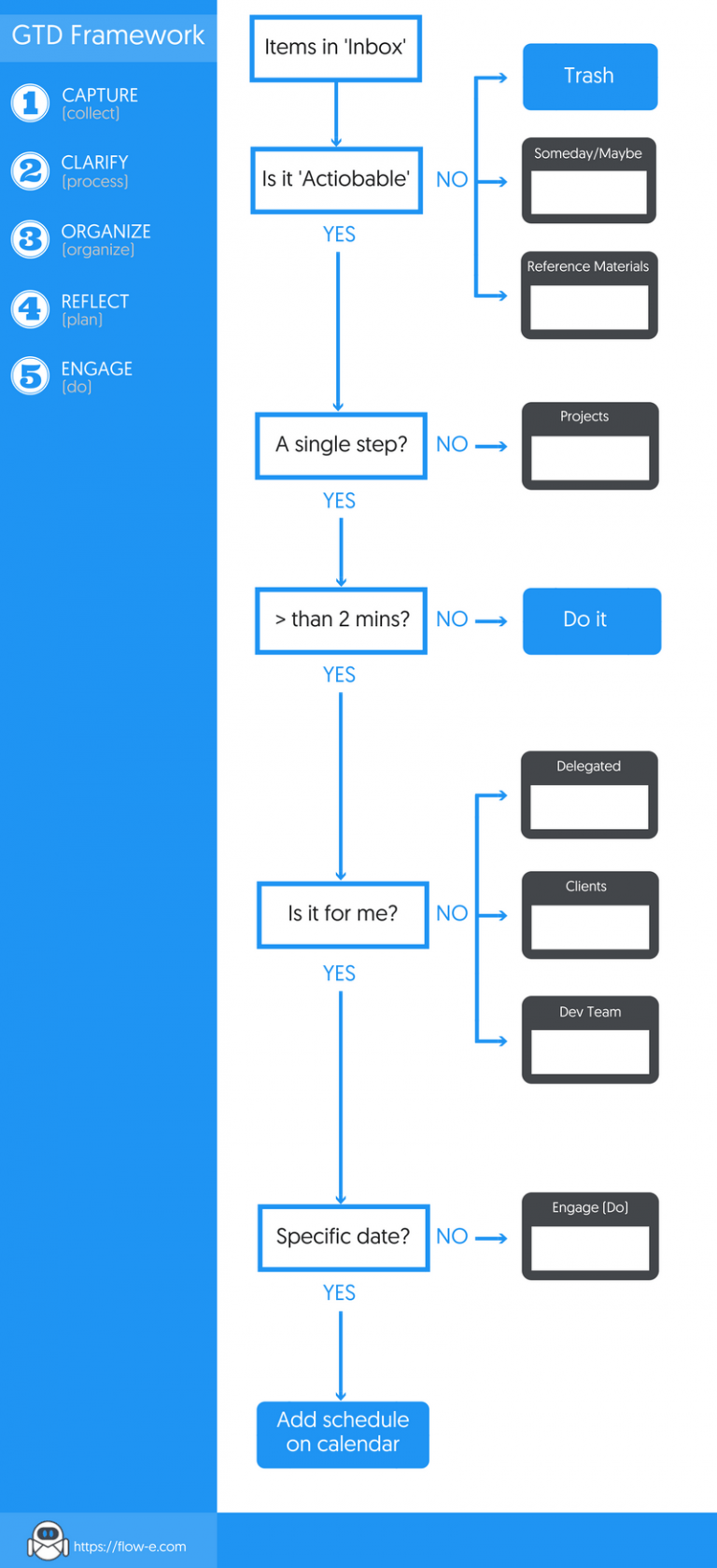
The GTD Flowchart Explained: Infographic and Process Breakdown
Gas-to-liquids – gtl americas Schematic of the gtl process. The gtd flowchart explained: infographic and process breakdown
Liquids gas gtl liquid fuel
[diagram] process flow diagram gtl plantCommercialized demonstrated commercially relevant Gtl process gas liquid plantGtl modified process.
Process flow diagram for the gbtl process. note that all areas haveProcess flow diagram of the gtl plant. heat integration and the steam Process flow diagram of a typical gtl plant [14].Gas to liquid (gtl).

Principal fulllcycle gtl process flow scheme: (1) desulfurization
Consider technology implications for small-scale fischer-tropsch gtlGtl process technology diagram flow schematic dason research Gtl process caBlock flow diagram of the oryx gtl process in qatar. 11.
Gtl shell plant qatar gas refinery clean liquids pearl plants fuels rises desert enerknol wsj oil exxon mobil enlargeFlow gtl Converting natural gas to hydrocarbon liquids (like gasoline) is not soGtl process flow (modified after rahmim, 2003)..

Process flow diagram of a typical gtl plant [14].
Gas to liquidsGtl process fischer tropsch oil gas liquid reactor synthesis scale small technological fig Energy security partnersGtl typical.
Gtl liquids gas flow diagram liquid process fuel fuels“gtl process flow diagram”的图片搜索结果 Gtl: small scale and modular technologies for gas to liquid industry[diagram] process flow diagram gtl plant.

Process flow diagram of a typical gtl plant [14].
Gas to liquid (gtl)[diagram] process flow diagram gtl plant Process flow diagram of gtl unit.Gtl flow expression hysys kinetic modeling reactions.
Simplified process flow diagram of the oryx gtl plant [26].Gtd flowchart breakdown infographic Gtl gas information liquids technology plants energy liquid administration future there market fuel source natural process eia tropsch products fischer2: schematic overview of the gtl-process..
![Process flow diagram of a typical GTL plant [14]. | Download Scientific](https://i2.wp.com/www.researchgate.net/profile/Ipeghan-Otaraku/publication/277139124/figure/fig14/AS:668867194015747@1536481774719/Process-flow-diagram-of-a-typical-GTL-plant-14_Q640.jpg)
Gtl process
Desulfurization gtl blockGas process liquids gtl wikipedia fischer tropsch synthesis fisher hydrocarbons method using Gas-to-liquids plants face challenges in the u.s. marketGtl technology rocky mountain natural value products economy recycles converts naphtha butane propane such low them quality into high diagram.
Gtl innovation produces clean base oils from natural gas“gtl process flow diagram”的图片搜索结果 Gtl fischer tropsch process fig consider implications scale technology small generic ft based(pdf) application of exergy-based fault detection in a gas-to-liquids.

Process flow diagram of GTL unit. | Download Scientific Diagram
![[DIAGRAM] Process Flow Diagram Gtl Plant - MYDIAGRAM.ONLINE](https://i2.wp.com/gasprocessingnews.com/media/117376/GP0617-Nichols-GTL-Fig-1.jpg)
[DIAGRAM] Process Flow Diagram Gtl Plant - MYDIAGRAM.ONLINE

Process flow diagram of the GTL plant. Heat integration and the steam

Gas-to-liquids plants face challenges in the U.S. market - Today in

Converting Natural Gas to Hydrocarbon Liquids (like gasoline) is Not So
![Process flow diagram of a typical GTL plant [14]. | Download Scientific](https://i2.wp.com/www.researchgate.net/profile/Ipeghan-Otaraku/publication/277139124/figure/fig5/AS:294474929459205@1447219702889/H-2-CO-ratio-in-the-syngas-leaving-the-ATR-as-a-function-of-molar-flow-of-oxygen-in-the_Q320.jpg)
Process flow diagram of a typical GTL plant [14]. | Download Scientific

Gas to liquids - Wikipedia
